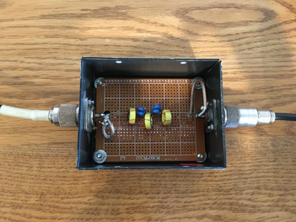
This year, SARA plans to include a VHF station in our yearly Field Day setup. While we have traditionally stayed on the HF bands at our Field Days, there is activity that occurs up on 6 meters that we hope to be able to take advantage of this year. As mentioned in the earlier post describing the TFD (Terminated Folded Dipole), we plan to use a single antenna with a number of filters on each of the HF radios. While we could add additional multiplexers in hopes of using 6 meters on the TFD, the complexity of the system is unreasonable, and even then, the performance of the TFD on 6 meters is sub optimal.
The VHF station captain (myself) decided for sake of simplicity to not attempt to use a 6 meter beam, but rather just a simple dipole on a 30 foot fiberglass pushup mast. Due to physical constraints on where antennas can be erected at the American Legion, the antennas for HF and 6 meters will likely be too close to avoid inter-station interference just by distancing the antennas. The 10 meter station will be using a band-pass filter which should reduce the second harmonic, which happens to fall near 6 meters. While that filter will help avoid the transmission of harmonics at 56 MHz (28 * 2), the radio being used on 6 meters will likely get overloaded or could even burn up from the excessive signal on 10 meters. To avoid damage to any of the radios, a filter designed for 6 meters that will reject signals from 10 meters is needed.
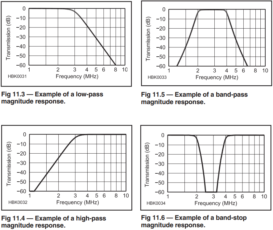
There are four different responses that filters can be built for. Since we need a filter that allows 6 meters through but cuts off 10 meters, either a 6 meter band-pass or high-pass filter would work.
As mentioned, both high-pass filters or band-pass filters would reject 10 meters, but since we also plan to run a 2 meter station that also may need filtering from the 10 meter station, we decided on the high pass filter since everything above 6 meters can pass through with minimal loss. While we would need separate band-pass filters for 6 meters and 2 meters if we hoped to run both VHF radios with close antennas simultaneously, the VHF station is designed for only one signal on the air at a time, so the filter can be swapped between radios.
Designing the Filter
To design the high-pass filter, I took advantage of an application called SVCFilter which was designed by Jim Tonne, W4ENE. That program and more can be found on their website at www.tonnesoftware.com. After installing the program, I entered in that the filter family should be Chebyshev, the topology should be an L-input high-pass filter, and the order should be 5. While this application is great for discovering the ideal capacitor and inductor values, there is a finite number of different capacitors, and a toroid-wound inductor with only 3 or 4 turns can only be so close to the required inductance. The software developers of SVCFilter saw this problem and thoughtfully included a feature that exports the model to an LTSpice file. LTSpice is an easy-to-use electronic simulator that can be used for about any circuit. By using LTSpice, I was able to enter the real capacitance and inductance values of my components and model what the circuit would be like.
Acquiring the Parts
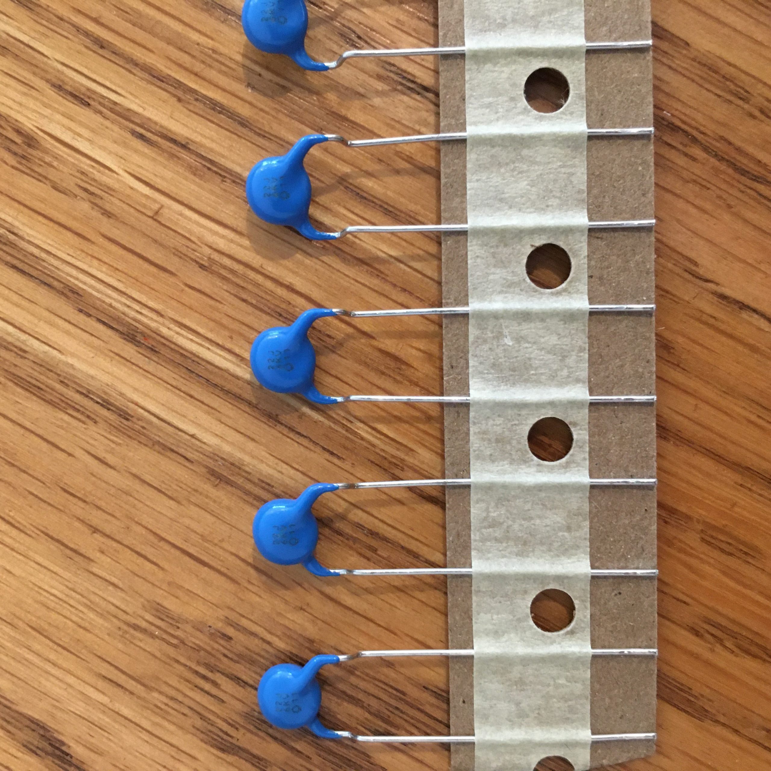 | Capacitors – nominal 22 pF ceramic disk capacitors. Two in parallel had capacitance around 48 pF. |
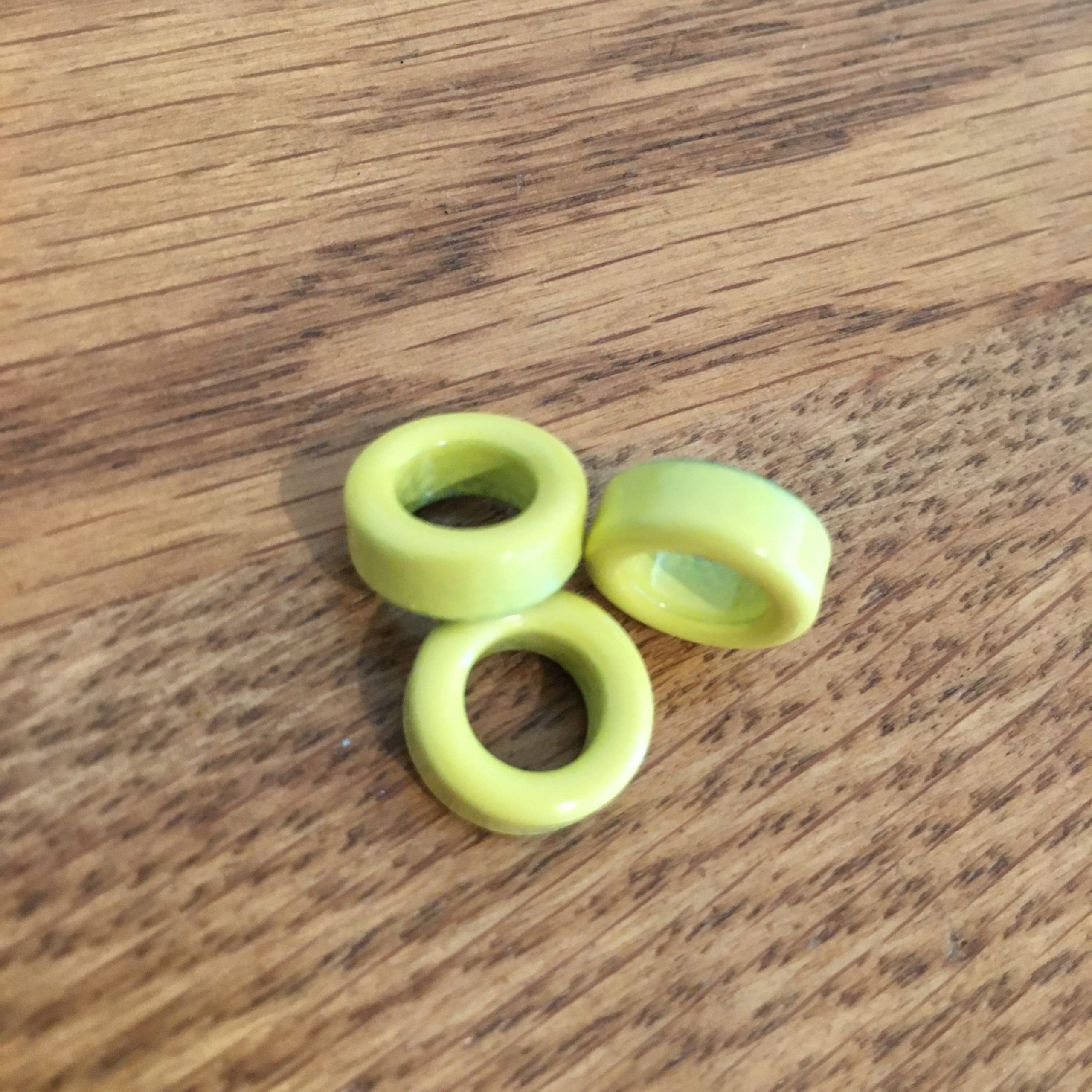 | 24 gauge wire wound on Micrometals T50-6 toroids. |
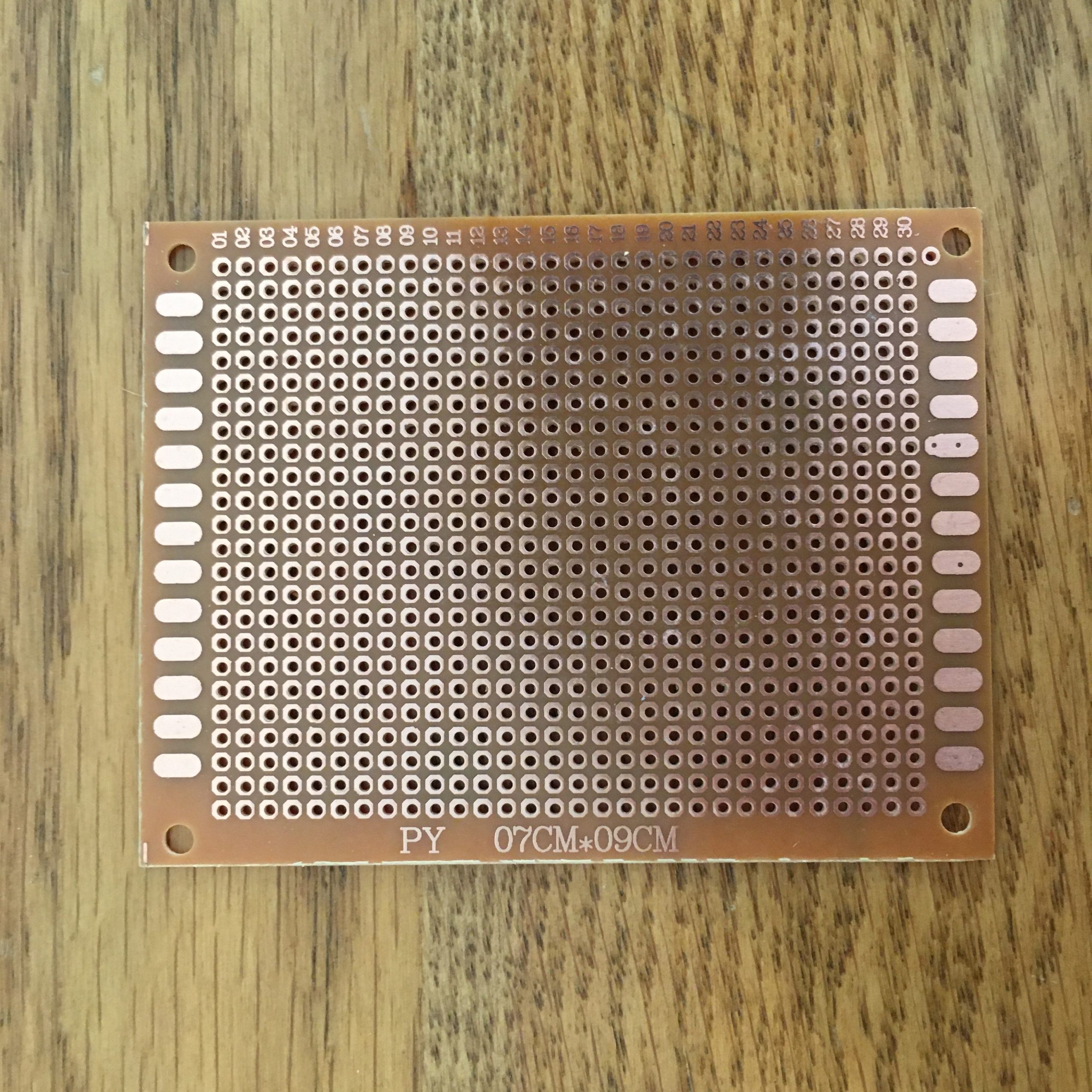 | Perfboard – 7 by 9 cm. |
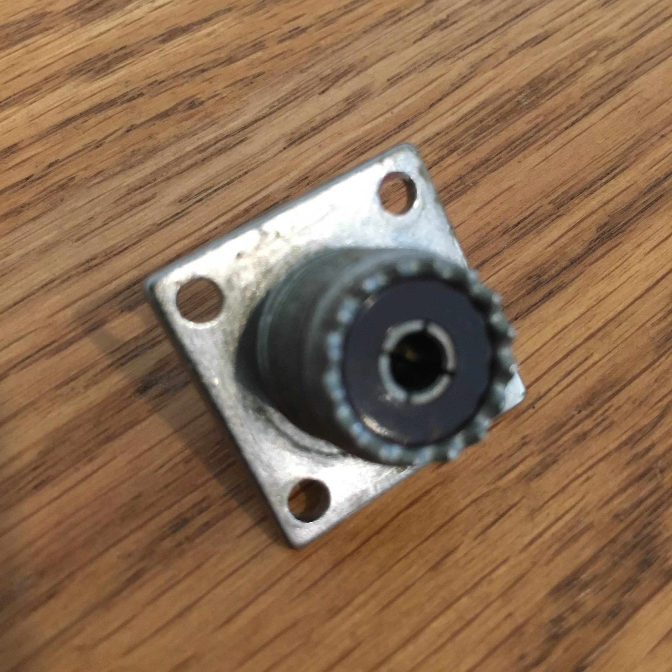 | SO-239 connectors |
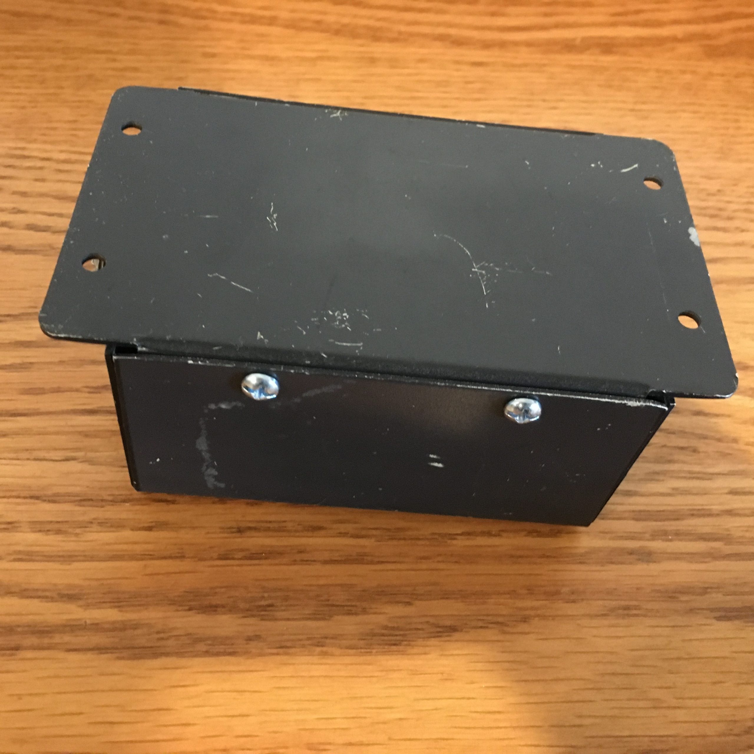 | Old metal enclosure |
Assembling the Filter
Since I didn’t know that the layout of the board was extremely critical, my dad and I simply connected everything as would be done for any other circuit. After doing a bit of testing, I discovered that the filter was not working at all as it should have been. After several conversations with Barry KI8B, I sent to him so he could help find the issues on the board. He quickly discovered that I had used considerably long wires in my ground connections, which ended up having a very high inductance on the wires. After he replaced the wires with a strip of copper foil and connected all of the ground wires to that strip, the filter performed very similarly to the LTSpice model.
Testing the Filter Attenuation
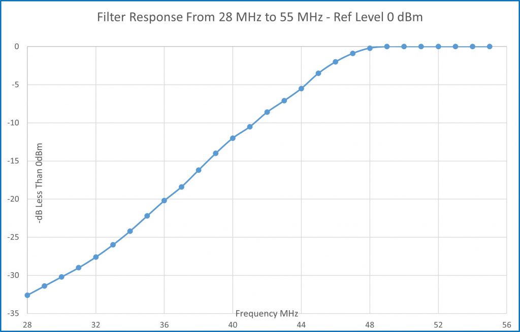
After Barry added the copper foil and made a few adjustments, he completed some testing with his spectrum analyzer. Since his analyzer can’t export a graph of the filter response, he tested the signal at every 1 MHz and entered the data into an Excel file to produce a graph. The graph shows that the filter has achieved a 30 dB rejection of 28 MHz, which is the standard for a 5 pole filter. The filter meets the attenuation requirement to avoid significant inter-station interference.
Power Handling Limitation
Unfortunately, I made a poor decision when choosing components to build the filter. A common error when making toroid wound inductors is selecting toroids that are too small to handle the required power. Choosing the correct toroid size is actually a compromise; larger cores can handle higher power, but since the inductance per turn is higher, it is more difficult to wind a large toroid to an exact inductance. Since the inductors for this filter only needed to be around 100 and 140 nH, each toroid had only 3 and 4 windings respectively. When I started to test the power handling capability of the filter, I was disappointed to find that the toroids became warm after a short transmission at 100 watts. After decreasing the output power on my radio, I decided to initiate the CW keyer within my logging software to auto-CQ for a while. As I increased the power of the transmitter, I could feel the toroids slowly becoming warmer. At 25 watts CW, the cores were slightly warm, but were definitely not hot. After letting the radio call CQ for about 20 minutes, I felt the temperature of the toroids and they were still just barely warm. Since the cores could saturate or even break due to extreme heat, we will limit our 6 meter output power at Field Day to 25 watts on CW as well as about 25 watts on compressed SSB. While it’s too bad that we won’t be able to run the full 100 watts, I think that it is better to accept having a signal that is 1 s-unit weaker rather then accepting a signal that is ∞ s-units weaker when the filter burns up.
While this filter was assembled without any accurate test equipment, it seems to performs quite well. The 6 meter station will have to run 25 watts or less if transmitting for any significant amount of time, but operating with 25 watts will definitely still be fun. Come out to Field Day 2021 and be sure to stop by the VHF station to experience the magic band.


