
The Silvercreek Amateur Radio Association operates and maintains two high-profile repeater systems to support amateur radio activities in the Northeast Ohio Area. Both repeaters operate under the W8WKY club callsign.
147.390 MHz – VHF 2 meter repeater on 147.390 MHz (+600KHz offset), PL (CTCSS) 114.8Hz in and out. Transmit power is 100 watts into the duplexer. This repeater is also connected to the AllStar network as node 43211, and the Echolink network as W8WKY-R node number 580387. Inbound Allstar connections to this repeater should use node 48496.
More details on the AllStar and Echolink connectivity can be found here.
442.275 MHz – UHF 70 cm repeater on 442.275 MHz (+5 MHz offset) running a digital multi-mode controller supporting DMR, D-STAR, Yaesu System Fusion, and P25. Transmit power is 100 watts into the duplexer.
Repeater Design and Operation
Repeaters are really just a separate transmitter and receiver, that are connected together with a repeater controller. Whatever is received on the receiver is re-transmitted on the transmitter. A great guide to how repeaters work by N4UJW can be found here.
Both of SARA’s repeaters are at the same physical location, which is a commercial tower and building owned by Marty Baker N8XPK. The two repeaters share a cabinet, power systems, feed line, and parts of the antenna system. The VHF and UHF systems operate as independent repeaters. The VHF repeater is controlled by an SCom 7330 repeater controller with an Allstar HamVOIP Pi cross-connected through the controller. The UHF repeater is controlled by a Pi-Star image running on a Raspberry Pi.
The VHF repeater’s output power is 100W into the system, but losses in the duplexers, feed lines, and other equipment mean that more like 80 watts actually makes it to the base of the antenna. The UHF repeater output is about goes into a commercial repeater amplifier with about 100 watts output, but losses in the components mean about 60 watts make it to the antenna. While this doesn’t sound like a lot of power, location is everything on VHF and UHF. These repeaters have a great location.
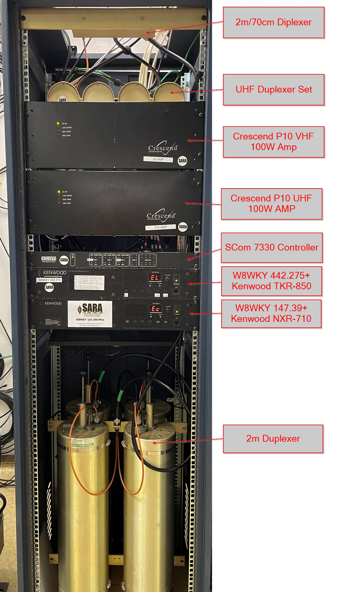
All of the repeater equipment is contained in a single 19″ rack at the repeater site.
Below is an annotated picture of the repeater cabinet showing the various components.

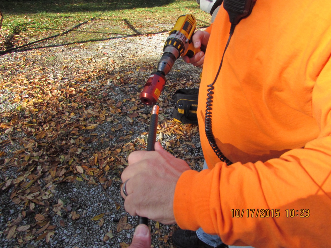
Both systems feed into coaxial cable that is much larger and much lower loss than most people use at home. The coaxial cable is known as Hard Line, and more closely resembles copper tubing than it does traditional RG8 coax. This 7/8″ cable is difficult to work with and bend where it is needed, so it has a short length (about 8 feet) of smaller diameter hardline at the repeater end to connect to the equipment, and another short length at the antenna end to reach to the antenna. The smaller diameter cable is shown below being prepared for connectors.
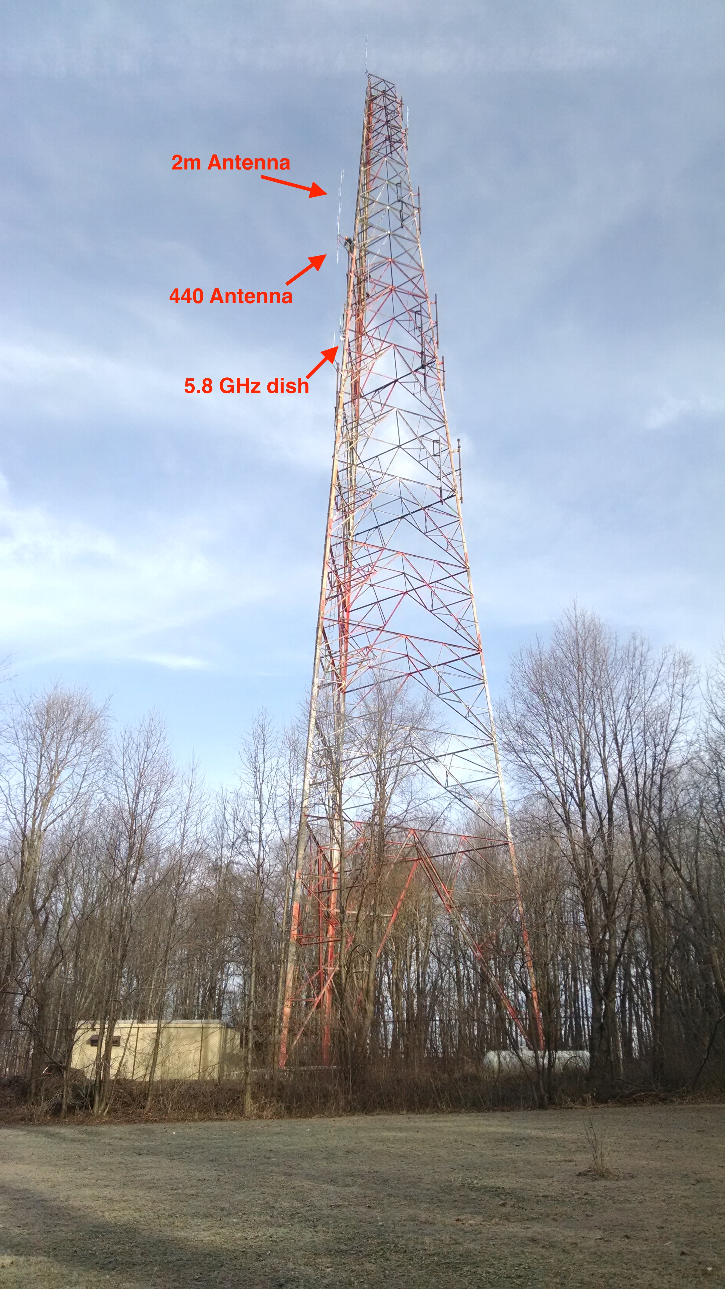
Finally, all the equipment connects through the hardline to a “crossband coupler”, which is an industrial version of the diplexer or splitter you might use on a dual band radio. This crossband coupler connects the VHF and UHF antennas into a single feedline. The picture below shows the location of the repeater antennas at the end of the yellow arrow. The VHF repeater uses a Commscope DB224 4-pole folded dipole antenna, and the UHF repeater uses a Commscope DB-411 4-pole folded dipole antenna. Also shown below the repeater antenna is the Ubiquiti PBE-M5-400 5.8GHz dish/radio combo used to provide data linking into the system.
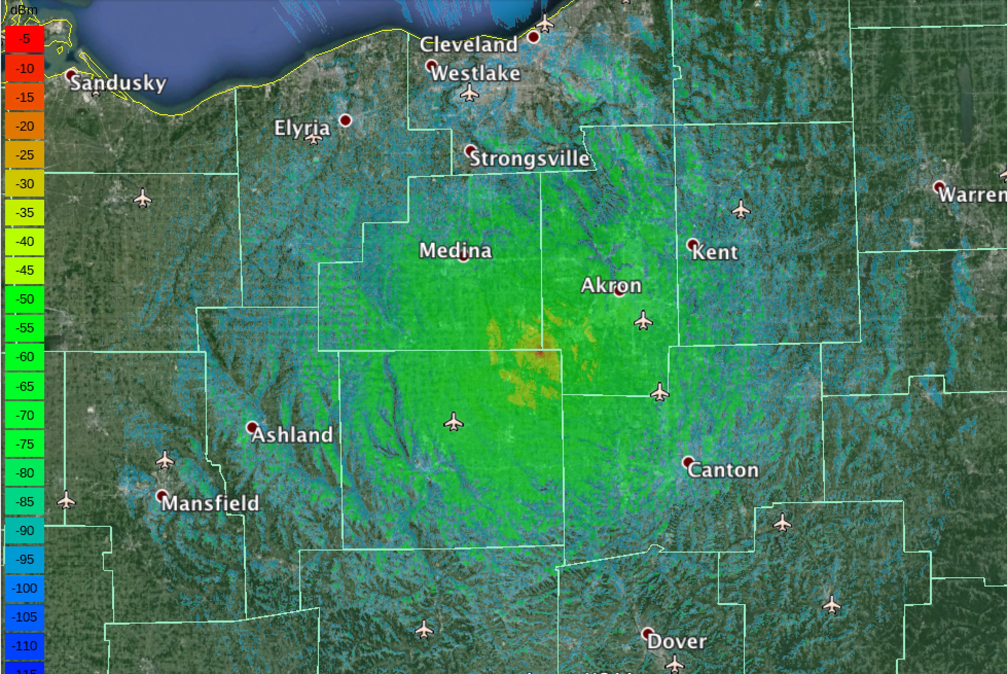
The result of all the above hardware and work is a coverage map for the VHF system that looks like the picture below (click the picture for a larger version). Note this propagation model is an average based on a mobile radio running about 10 watts and a 1/4 wave antenna. Coverage will likely be significantly better for base or improved mobile installations. The green color is solid coverage, and the blue coloring shows more marginal areas. Coverage for the UHF repeater is slightly less than the VHF model, but is almost exactly the same pattern.
Compared to most ham’s home stations, there are some big differences in what repeaters experience:
- They are powered on 24x7x365
- They often are transmitting for several hours at a time without a break
- The antennas cannot be disconnected when storms approach, so they are exposed to lighting and other hazards
- The extreme height of the antenna exposes the antenna to more wind, ice, snow, and other conditions than most home systems
- The antenna height also exposes the repeater to more RF noise from other near and distant radio systems, repeaters, cell towers, lightning static, and electrical noise than most home systems experience.
- Repeaters must be operated under the coordination of the Ohio Area Repeater Council
Over the 35+ years that the 147.390 VHF repeater has been on the air, it has evolved from re-purposed commercial equipment controlled with home brew controllers based on discrete TTL chips and transistors to the more modern, purpose built commercial radio systems they are today.
Enjoy the SARA repeater systems!