
The new Bridgecom repeater and Henry amplifier, along with all new cables, power distribution, and repeater controller were all installed on Saturday morning, May 15th 2016. This installation is the result of the incredible response for the club in the recent fund drive to replace the radio gear behind the 147.39 repeater. All of the pictures from the event can be found in a photo gallery here on our website, or as a link from the “Photo Galleries” menu at the top of the page.
The weather on this Saturday morning was a lot like the weather when the new repeater antenna was installed last year. We didn’t actually see snow flakes this time, but it was unseasonably cold, rainy, and windy. At least all the work was indoors for this effort. Something about major repeater work by our club apparently has a short term impact on global warming.

In the week leading up to the assembly day, Barry KI8B documented how everything should interconnect and be assembled, complete with CAD drawings. All of the new equipment was interconnected at KI8B’s QTH to ensure it all worked together as designed, followed by interfacing and testing of the controller with the new repeater at N8CD’s QTH. Finally, it was all loaded up for delivery to the repeater site.
Through the day, Barry KI8B, Del N8OFP, Gary AA8CS, Marty N8XPK, and John N8CD stripped everything out of the repeater rack, laid it on the ground, and started over.
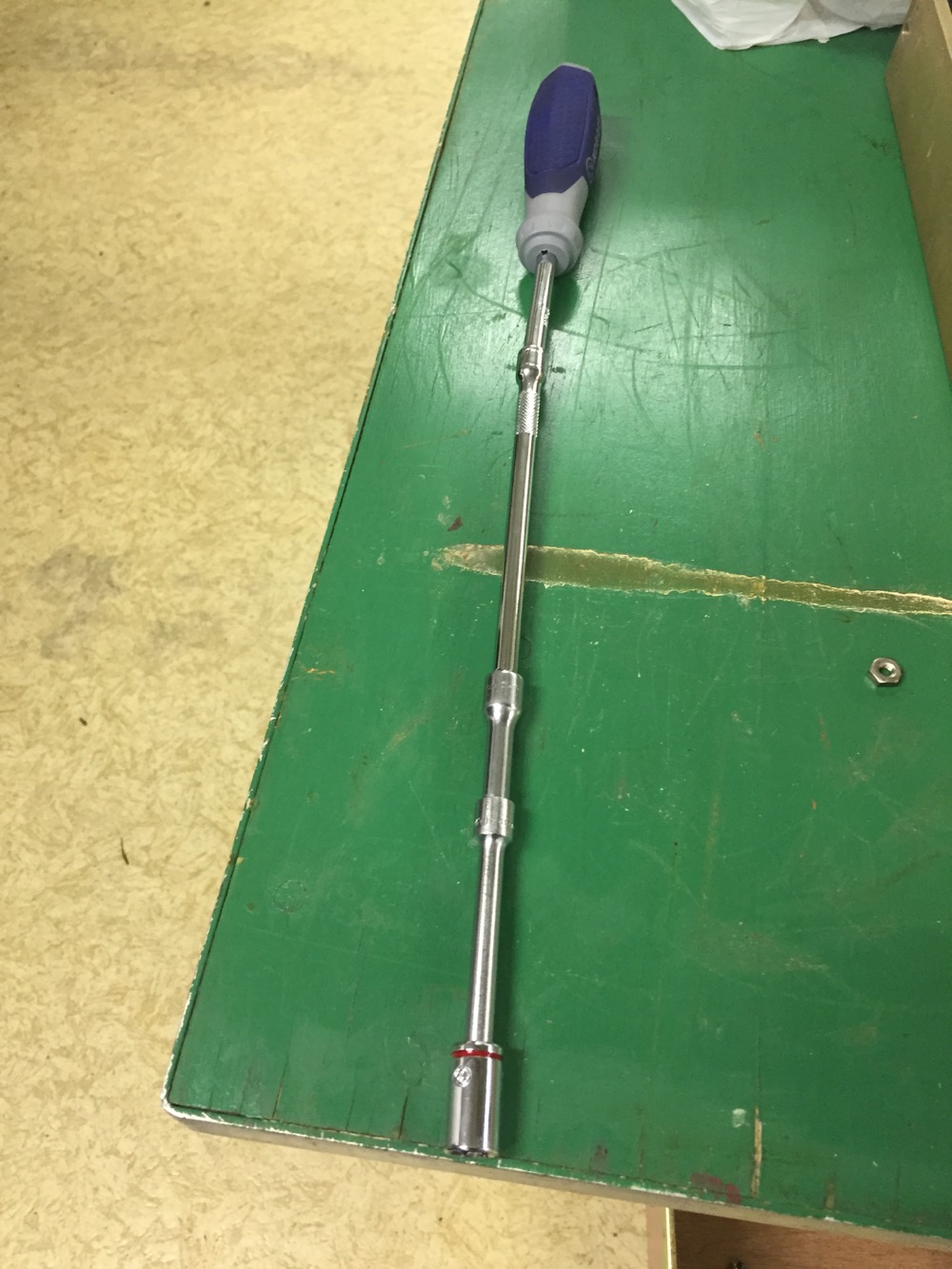
If you think repeater work is all about electronics, check out this improvised tool used to get at some nuts in a hard to reach location of the rack.

Right after 9AM, the SARA VHF and UHF repeaters were powered down and the work began. Everything was removed from the rack with the exception of the VHF duplexers to allow for ideal position for all the new gear.
Some drilling and tapping was required to get the gear in the ideal position. The main gear was in the rack and it was stood back up by 11AM. Just in time for the lunch delivery by Bob W8IJG. Bob has a reputation for feeding SARA some amazing food, and he did not disappoint. Lunch included Sicilian sausage and peppers that had been cooking since 6 AM made into sandwiches, along with some of the best chips around. Everyone agreed that the sausage was hands down the best any of us has ever had. The lunch was topped with some fantastic chocolate chip cookies.

After lunch, Barry KI8B fired up the RF cable factory and produced what we now refer to as “certified cables”. All the VHF RF interconnection cables were replaced with LMR-240 double-shielded cable and new N connectors. At the same time, Del N8OFP assembled new DC cabling and interconnected the power supply, both the VHF and UHF repeaters, controllers, battery, and chargers.
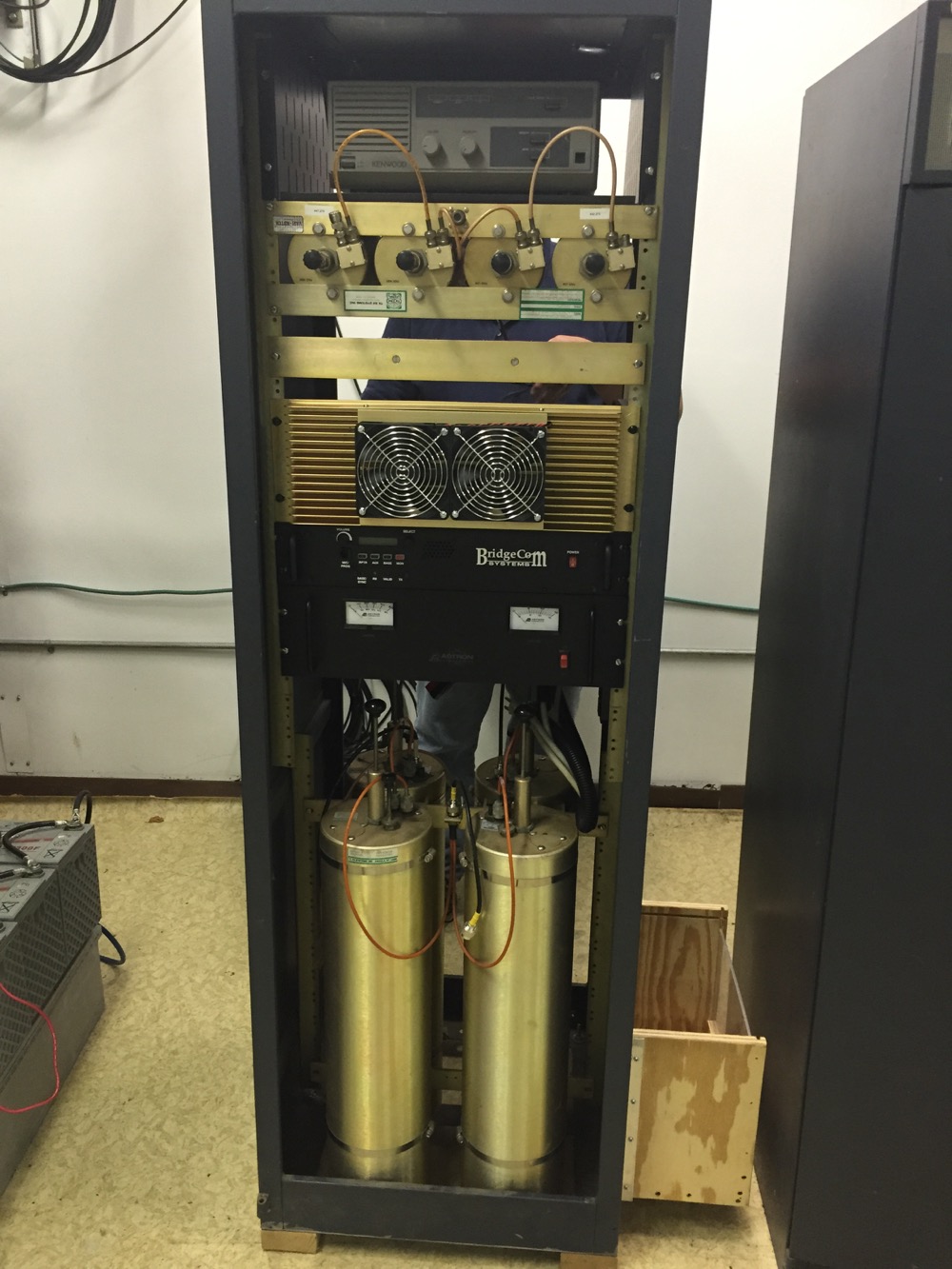
The new gear that was installed in the cabinet included:
- Bridgecom BCR-50V repeater
- Henry Radio C130AB10R 100 watt continuous duty amplifier
- Astron RM-50M power supply
- All new LMR-240 double-shielded coax cable and N connectors
- Raspberry Pi 2 repeater controller (re-purposed from 39’s old Allstar/Echolink controller)
- New DC wiring, connectors, and power relays
- New and safer backup battery enclosure and battery charger
With everything wired up, both the VHF and UHF repeaters were tested into dummy loads, audio levels were roughed in and adjusted, and power measurements were taken. The final specs from the completed install:
VHF repeater:
- RF Output from the Henry Amplifier: 95 watts
- RF output on VHF after losses from the duplexer and VHF/UHF splitter: 58 watts
- Current draw from the power supply while transmitting: 22 amps
UHF repeater:
- RF Output from the Kenwood UHF Repeater (no amplifier): 22 watts
- RF output on UHF after losses from the duplexer and VHF/UHF splitter: 12 watts
Thanks go to everyone that helped with this effort in any way, including financial, design, assembly, culinary art, and moral support!
